GREDDY PROFEC B II Installation
(will be updated upon
completion - need to get hoses set up to control solenoid)
Thanks as usual to TT.net and it's members for responses and
archived, searchable posts : )
Installing the Greddy PROFEC B II on a 300zx is really quite simple and the Profec is also among the most simple of EBC's -- it gets the job done!
There have been numerous posts asking how to install the GREDDY. This is probably because the TECH document for install of the APEXI unit (APEXI Super AVCR INSTALL) is much more complicated and can confuse those installing the less involved Greddy PROFEC. With the PROFEC, you only NEED to make one wire splice (finding a 12V) and then run the Greddy wiring and vacuum hoses - also a cinch. You won't have to mess with the ECU at all (no splicing into the ECU). The PROFEC B II takes about 1/4 as much work as the APEXI. That said, let me now write MORE THAN NEEDED about installing the GREDDY : )
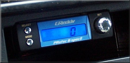
Before I provide install information, including the ever popular "where did you mount it" answer, I want to point out one thing about the PROFEC B II:
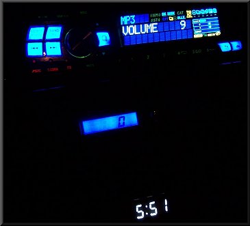
The PROFEC boost gauge is a BOOST GAUGE only. It was not designed to provide an accurate VACUUM reading. When I set up my PROFEC, it was oly reading 8 in-hg of vacuum. I emailed GREDDY about this and they told me there was nothing wrong. You may also wonder if the unit is reading boost correctly -- since this is a digital gauge, it might be tough to see what you are actually boosting to. The unit will record your PEAK BOOST which you can look at after a run to determine what it is actually reading. RESET the Peak Boost reading, do another quick run, and and you can confirm PEAK BOOST for that run. The latest PEAK BOOST will remain in memory even if you turn off the unit.
So, before you feel silly for
installing an aftermarket boost gauge and then install a PROFEC,
don't feel too bad...it's probably useful to have an accurate
vacuum gauge in the car.
INSTALLATION
Basically you are going to follow the writeup provided on TT.net for the APEXI unit, but as mentioned above, with less steps. There are a few other PROFEC install writeups floating around - here is one. I'm trying to find another one that I ran across so I can add that link. Here are my thoughts on the process.
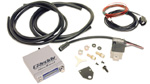
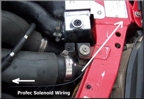
Wiring
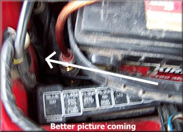
I ran the Greddy control solenoid wiring by starting up at the front of the car. I ran the "white clip" side of the harness through around the radiator, around the pass side strut tower (passing it under things where I could), around the battery (I did not have to remove my battery), feed it through the hole by the side of the battery, and then through the pass-side tire well harness entry (exactly as explained in the AVC-R writeup - you'll want to remove the ECU cover and the passenger side kick panel for access to the wire from the inside). I decided to take an Exacto knife and cut right into the side of the rubber grommet and feed the small line right through. From there, just locate the harness from inside, pull the slack through from the inside and route it safely up to the DIN unit. I have mine routed above all the A/C plastic brackets above the ECU.
There was plenty of cable to reach to the DIN pocket with enough slack (maybe a foot) for comfortable installation. If you need to extend the wire for whatever reason, it should be easy to splice in some extra wire.
Now splice in the 12V power (red) from the Greddy harness into the clock harness (12V switched line - green). Connect a spade or ring connector to the ground (black) and make sure to ground it before putting the dash all back together.
Boost Gauge Hose
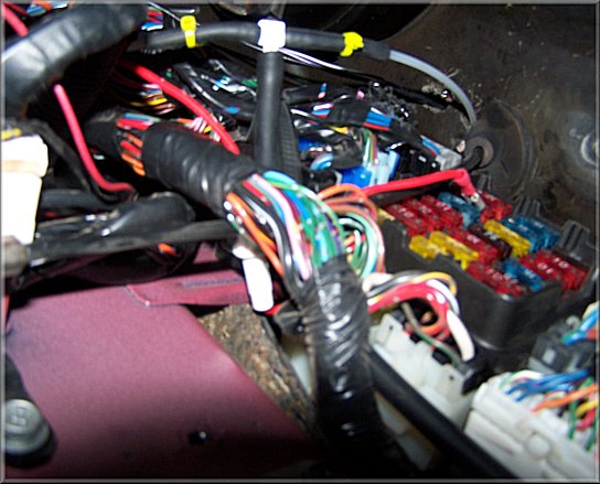
If you already have an aftermarket boost gauge installed and you don't want to run a new vacuum line to the PROFEC, you're in luck. 'T' into the existing line and just run it to the PROFEC (see below). I cut the nylon hose to my Autometer and used small sections of 1/4" vacuum hose, a 1/4" x 3/16" x 1/4" 'T', and two small zip ties to secure the nylon hose into the 'T'. Then the 3/16" hose (4mm) supplied with the unit runs from the T, down along the fuse panel, then behind the driver's side carpet, and up to the center console area. Make sure the vacuum line isn't loose around the gas pedal and able to interfere/get caught.

If the existing boost gauge hose has a smaller diameter than the Greddy hose you run, you might see a very small pressure reading difference to the Greddy -- I'm actually have not confirmed if this is a fact -- let me know if you know. As seen above, my AUTOMETER gauge uses a very thin NYLON tube, which is a nice material for running through the firewall. The PROFEC uses 4mm (~3/16"). The Autometer reads around 11 peak PSI (analog) while the Greddy reads 10.5 (digital). This difference is small enough that a) it doesn't matter enough to hurt anything b) the difference is in the gauge calibrations c) it could just be my anolog gauge is really reading 10.5, not 11 : )
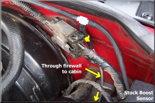
My Autometer nylon line is tapped into the stock boost sensor hose for my signal to inside the cabin. I used to have it set up on the FPR line, but I found it annoying to get the oil dipstick out with the line tied in there. By tying into the stock hose, the connection is hard to see and out of the way. Three boost gauges on one line (stock, Autometer, and Profec). If you have any questions about how to get this line from the engine bay to the cabin, follow the BOOST GAUGE install TECH.
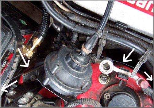
Wastegate Hoses
The wastegate vacuum hoses are simple to reroute to the Greddy control solenoid. Unplug stock wastegate hoses connected to nipples on the intercooler pipes that lead to the Throttle Bodies. Once disconnected, take a long length of 1/4" hose, connect to one side, run around the side of the radiator and around the front, then around the other side back toward the engine, and connect to the other nipple. Cut the loop in half in front of the radiator, use a 1/4" 'T' and connect the ends you just cut. Then run a short line down to the NO port on the Greddy control solenoid.
Then, with one of the original hoses you removed from the nipples, attach a long length of 1/4" hose using a barrel connector. Wrap around radiator and back to the other original hose and connect with another barrel connector. Cut this loop in half like you did on the first, and connect to another 1/4" 'T'. Run a short line down to COM port on the Greddy control solenoid. You can optionally remove the original wastegate hose and run a line all the way down to the wastegate actuators, 'T' together in front of the radiator and run a short line to the Greddy control solenoid.
Either use ZIP TIES or appropriate hose clamps to secure these connections. To see a great example of how the hoses should be routed, visit here.
Now unplug the wastegate solenoid electrical connectors (one on each side of the engine).
It's honestly that simple!
MOUNTING LOCATION
I did a lot of seaching and flip-flopping about where to mount the unit. I like installation to look clean, but also be pretty simple with limited modifications to any mounting areas. I liked the idea of installing it under the dash as done here (DEEP-PURPLE). This is probably the coolest installation I have seen. However, I decided against it for a few reasons. 1) I had an airbag warning sticker on the left side that I didn't want to remove. 2) I didn't want to cut off the lower dash plastic clips. 3) Although very cool, the process looked quite extensive, requring time and precision. Props to Deep-Purple for the good job, though!
Here's another GREAT idea -- buy this HKS DIN fascia! At $70, it's a pretty penny, but sure would look good with the GREDDY units and some gauge (Fuel Pressure or maybe a voltmeter : ) I assume they'd fit.
Next I thought the stock clock area would be good, as many have done. But my clock still works and I figured I'd keep it there.
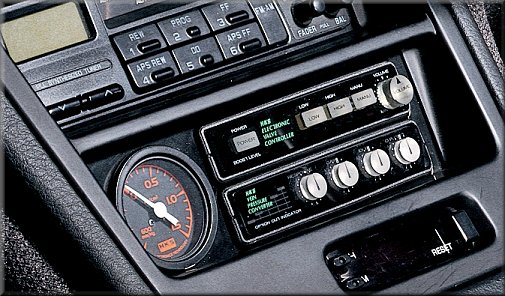
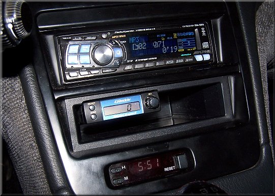
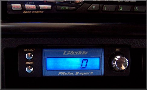
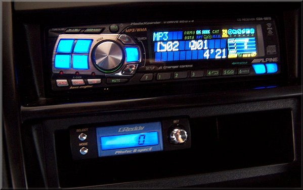
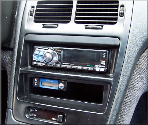
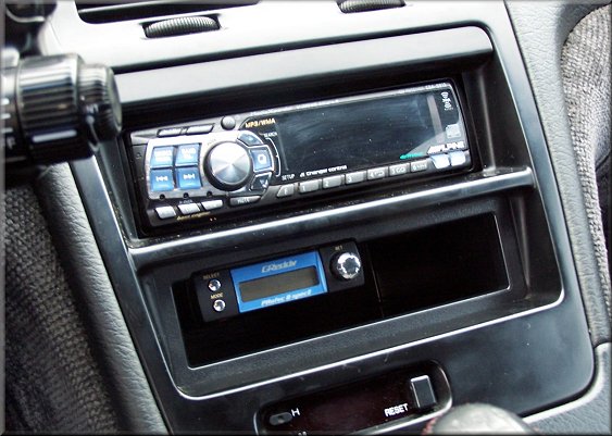
I decided to mount the unit in the lower DIN POCKET. I didn't want to buy and shape a piece of ABS board or use up the entire space with the little Profec box. I didn't like the way the unit looked sitting at the bottom of the DIN pocket (plus dust could settle on it that way). I also wanted it to be "somewhat" hidden. So, I decided to mount it underneath the upper lip of the DIN pocket, and I think it turned out great.
I did some markings on the plastic and went to town with a DREMEL. I wanted it to look like it was supposed to be there. I ground down a bit of the DIN finisher to contour the PROFEC unit, as you can see in the two pictures below.
In the rear, I simply cut a rectangle just bigger than the GREDDY for easier access to the plugs in the back (for the future). I hooked up all the connections, inserted the unit from the hole in the back, made sure the vacuum tube wasn't pinched, and then used the THIN double-sided foam supplied with the unit to mount it to the top. Once it goes on, it stays on. I wanted to push it back just a bit because it was a bit more exposed than I wanted, but the FLUSH look is probably cooler anyway. I think the look is good, great access, and hard to get out (minor theft deterant). The double-sided foam holds the unit firmly - doesn't move at all when pressing buttons. Also, by using the DIN pocket, if I ever decide I don't like the mount area I can replace the DIN pocket for a few bucks and have things back to normal. I can still stuff a few couple CD jewel cases in the pocket, or a ticket from Highway Patrol : )
TUNING/SETUP
I have not tuned my PROFEC yet as there are some other issues I'm fighting right now - namely, poor power/acceleration above 4500 RPM. My boost is setup up stock right now (boosting to 10.5 because of mods). I was boosting 15 without detonation, but something funny is happening in the upper band. Once I get that figured out, I will actually put this thing to some use.
Anyway - here are a few links I have bookmarked for fine-tuning the PROFEC.
ASH: Recommended Settings
WHITEPEARLZ: Installation Guide and Beautiful Hose/Solenoid Setup
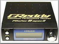
PROFEC B-SPEC2
ONLINE MANUAL (.PDF) 3.78 MB |
|||
|---|---|---|---|
| Based on the very popular B-Spec., the all new PRofec B-Spec. II's basic function to increase boost is as easy as the original, with an added built in boost pressure display and optional features like real-time, peak or last boost display (in either kPa or PSI). There are optional warning and boost limiter functions that can be programmed to offer much more control. The two presets values can be stored and are executed by a larger capacity inline solenoid valve. This unit does not require extensive programming and is ideal for low to high boost levels for single or twin turbos with actuator or external wastegates. The GReddy PRofec B-Spec. II is available in black or silver cased head units. | |||