![]()
![]()
![]()
![]()
![]()
![]()
![]()
![]()
![]()
![]()
![]()
![]()
VACUUM HOSES & CONNECTED COMPONENTS GUIDE Return to Boost Leak Location Guide
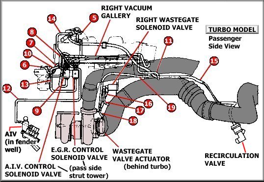
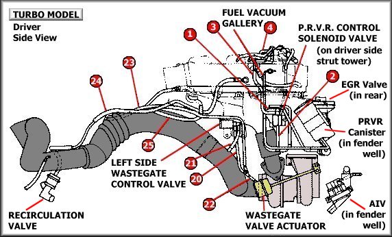
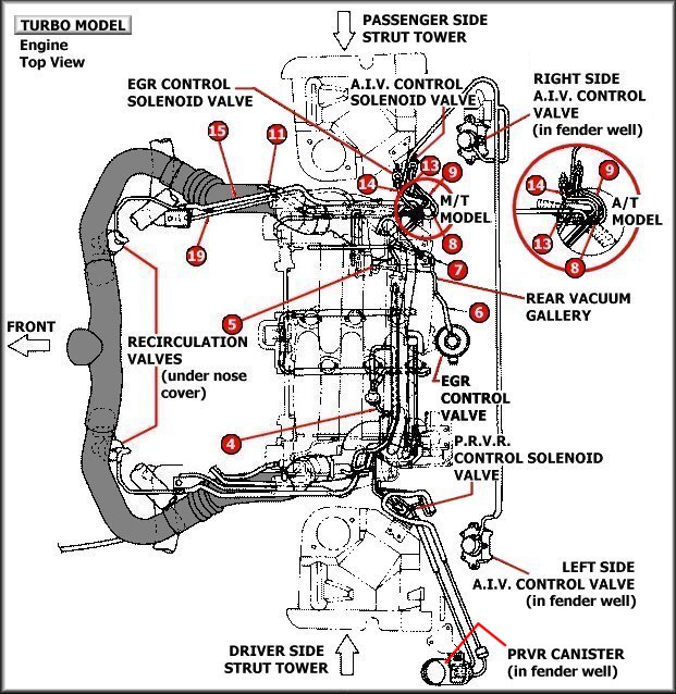
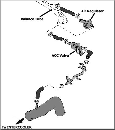
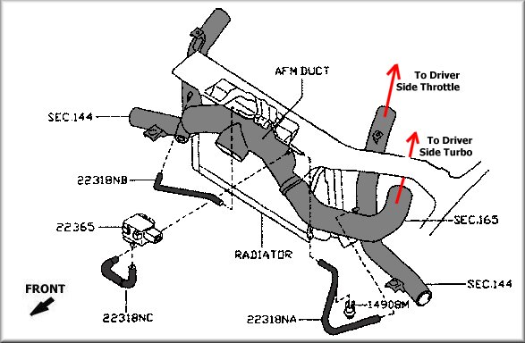
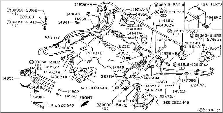
Below is a complete checklist of devices connected to vacuum along with Nissan diagrams (slight aesthetic/readability modification). You should be able to follow the vacuum lines in your car pretty effectively with these diagrams. Note that ANY OF THESE devices or their associated hose/clamps could be defective/loose resulting in VACUUM/BOOST LEAK! Refer to your engine bay along with these diagrams. Instead of just seeing a tangled web of hoses, you will gain understanding of the vacuum system design, which should help you pinpoint problem areas and facilitate fixes.
The only TECHNICAL change I made is the location of the AIV and EGR solenoids. It has been noted by most Z owners (as they remove their AIV systems) that the AIV solenoid is usually the one located closest to the battery. The Nissan diagram shows the EGR closest to the battery. These valves look identical. You should be able to tell quickly which is which on your car by following the connected vacuum lines to their respective devices. A hose, gasket (to housing), or hose clamp will inter-connect each component to the manifold, air gallery (vacuum hardline), or to another device that can be under vacuum.
| Itemized List of VACUUM DEVICES Includes all items connected by a Vacuum Line IF YOU THINK OF OTHERS, PLEASE EMAIL ME! |
Intake Tract:
Air Galleries (vacuum hardlines):
|
EGR Control Solenoid EGR Valve AIV Control Solenoid Passenger Side AIV Passenger Side AIV Actuator Driver Side AIV Driver Side AIV Actuator PRVR Solenoid PRVR Canister Passenger Side Throttle Chamber Driver Side Throttle Chamber Passenger Side Recirculation Valve Driver Side Recirulation Valve Factory Boost Sensor Balance Tube Passenger Side Valve Timing Solenoid Valve Driver Side Timing Solenoid Valve |
Balance Tube IAA (Idle Control Valve) Canister Purge Line A/C and Heater Control (???) Clutch Vacuum Assist Break Vacuum Assist Driver Side Wastegate Driver Side Wastegate Actuator Passenger Side Wastegate Passenger Side Wastegate Actuator Fuel Pressure Regulator Fuel Damper Air Regulator FICD (Fast Idle) All vacuum hoses (too many to list) Intake Tract Hoses Turbos PCV Valve System |
To make reading the diagrams below easier, you may want to print out the following numbered list and refer to it as you view the diagrams. The numbers refer to (and point to) vacuum hoses, though it may be a bit tough to see from the wonderful, high resolution of these diagrams (note sarcasm).
|
|
|
PCV Valve System
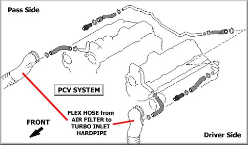
INCOMPLETE GRAPHICS -- May be helpful for now, anyway.
![]()
![]()
![]()
![]()
![]()
![]()
![]()
![]()
![]()
![]()
![]()
![]()